Showing posts with label 2SK1058. Show all posts

Tuesday, 16 June 2015

DIY DC/DC Dual Boost regulated Power Supply for High Voltage Tube VAS


In relation to DIY Hybrid amplifer the first step is to obtain the High Voltage for tube's anode supply and the low voltage for heaters.

Sometimes, if not always, fora a 100W amplifier you have a double sec 150-300VA  36-0-36Vac power transformer only.
Using this board you can adjust the  needed voltage for tube stage starting from your transformer.
Without use any voltage doubler and linear regulators.


The Following image shows how the Double Boost works.
From unregulated  +55/0/-55Vdc the circuit gives at his output the needed voltage, able to supply the anode current for a tube stage.
For example you can obtain +90/0/-90Vdc and 6.3Vdc for the heaters..




Friday, 12 September 2014

Luxman LV-105 Style Hybrid Amplifier 100W Simulated Project 6DJ8 (ECC88) Hitachi Mosfet 2SK1058 2SJ162


Similar to basic schematic of Luxman LV-103 / LV-105 , this project is made by only 3 simple stages: 

  1. Input stage: is a BJT cascode(Q8,Q9) with current sink(Q11)
  2. VAS stage: is a 6DJ8 (ECC88) SRPP (X7,X8) buffered by a emitter follower BJT (Q10) with MOSFET current sink (M9)
  3. Output stage: is a B class Mosfet Push Pull  with two couple of 2SK1058 / 2SJ162  Hitachi 


100W Schematic 


Simulated FR


Simulated Distortion 0.041% at 32Vpp out


Tuesday, 20 May 2014

100W Mosfet Amplifier Project STK3102III 2SK1058 2SJ162


Mosfet Amplifier Project.

Components:

Amplifier Module Driver           STK3102III           Sanyo
Lateral Audio Power Mosfet    2SK1058 2SJ1062 HITACHI


Output Power Stage


STK3102III Stage
Download Full Schematic:


STK3102III Amplifier PDF


Wednesday, 5 February 2014

Hybrid Power Amplifier Using 12AX7 as Input Stage and VAS, 2SK1058 - 2SJ162 as Current Buffer

In this days I'm working around an Hybrid Power Amplifer
Below the Microcap Simulation Schematic

M2 and M2 are Hitachi 2SK1058 Mosfet
M3 and M4 are Hitachi 2SJ162 Mosfet

Bias current is around 100mA

V1 and V5 are High Voltage Supply, around 300Vdc
V3 and V4 are 50Vc for Power Stage

X4 is TL071 Op Amp used to fix to 0Vdc the ampli's voltage offset.

The Negative Feedback Network is present

X3 is a SRPP as Input Stage
X1-X2 are used as VAS and to drive the Power Mos Stage

Tuesday, 22 October 2013

Mosfet Amplifier 100W Example Schematic: AB class Principle Diagram


The Following Schematic is an Example about Easy Implementation of Mosfet Power Amplifier.
Power Supply is not regulated.
AB class operating.
100W could be obtained in 8ohm load.
Mosfet 2SK1058 2SJ162.Mosfet Amplifier Example Schematic


Mosfet Amplifier Schematic Example

Dowload PDF schematic document:


Tuesday, 14 May 2013

HTA: Hitachi Top Mosfet Amplifier 100W Project Using 2SK1058 2SJ162


 Hitachi Top Mosfet Amplifier Project

All Semiconductors, BJT - Mosfet.
Only Schematic.

Download Mosfet Amplifier Schematic pdf

Description:
HTA: Hitachi Top Amplifier
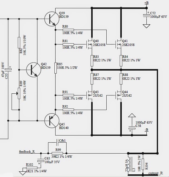
B Class Mosfet Power Amplifier, using Hitachi's Mosfets 2SK1058-2SJ162.
Input differential stage and VAS stage are like Sony's ES 90's  amplifer.
VAS is Cascode Configuration.
Output Stage use 4 devices, 2 N channel MOS and 2 P channel MOS, note the power voltage rail is NOT regulated, the signal voltage should be... anyway they must be separated.

100W Continuos Power into 8 ohm could be obtained with appropriate Power Supply


Hitachi's Mosfet Amplifier Project