Showing posts with label Class A. Show all posts

Wednesday, 25 December 2019

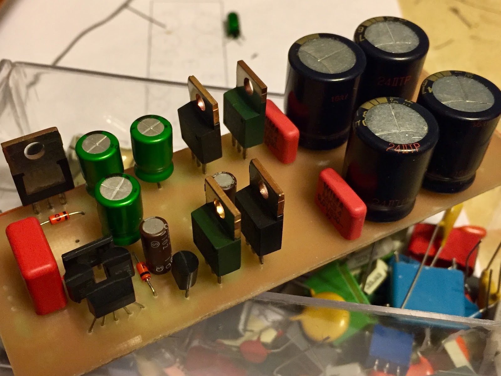
High End Preamplifier Module for TA-E901


The Ultimate HI FI Design Sony ESPRIT
High End Preamplifier Module for TA-E901 and TA-E900 Sony #ESPRIT Replacement
All Resitors are 1206 SMD Thin Film 1% Tolerance
Two Layers PCB
Last Generation #BJT and J-FET

#ALTIUM
#SONY
#HIFIAUDIO
#higend


Tuesday, 22 May 2018

EL34 Triode connection Push Pull CFB Paraphrase Inverter Amplifer Schematic from Bartolomeo Aloia Project and Hammond Transformer


This is my first Tube Hi Fi amplifier, I choose to start from a  Bartolomeo Aloia project :
VTAF Volks Tube Amplifier The First by Bartolomeo Aloia
 you can find details on audiodesignguide page.

The project is based around a EL34 triode conection push pull.
The output transformer is a Hammond 1615 witch I would use in Chatode Feddbak connection.

Paraphrase imput stage and phase splitter is a  modified GY50 driver stage board .


Phase Splitter Prototipe Paraphrase inverter


EL34 triode push pull CFB amplifier schematic

Thursday, 5 January 2017

Tuesday, 22 November 2016

Next Power Amplifier based on Sony Esprit Series Using No Negative Feedback Architecture


I'm traying to make an amplifier following example of Sony TA-N902 Esprit Sere, the last aftre TA-N900 mono and TA-N901 stereo.
Sony's Esprit  amplifier all haven't Negative Feedback, they had a Voltage Amplifier Stage made by discrete components, which has his proprer feedback and a current stage located out the loop, This architecture decrease the TIM distortion. To minimize THD Sony used his own  patent concerning non-switching power devices, the stage also remain a AB class but  results similar to pure class A.


3D of the  Voltage Amplifiere Stage


Some amplifier are been used as example for schematic or as  components donor.

Power supply is from a PLPS from an old TA-F80,electronic components for VAS are coming from a TA-F500, the chassis is given by a broken Behringer A500.
Other components are new and PCB are made by myself.


Current Amplifier 3D


I used a lot of SMD components, all with 1206 dimension

Soon I'll show the complete work


Tuesday, 16 June 2015

DIY DC/DC Dual Boost regulated Power Supply for High Voltage Tube VAS


In relation to DIY Hybrid amplifer the first step is to obtain the High Voltage for tube's anode supply and the low voltage for heaters.

Sometimes, if not always, fora a 100W amplifier you have a double sec 150-300VA  36-0-36Vac power transformer only.
Using this board you can adjust the  needed voltage for tube stage starting from your transformer.
Without use any voltage doubler and linear regulators.


The Following image shows how the Double Boost works.
From unregulated  +55/0/-55Vdc the circuit gives at his output the needed voltage, able to supply the anode current for a tube stage.
For example you can obtain +90/0/-90Vdc and 6.3Vdc for the heaters..


Friday, 5 June 2015

DIY Do It Yourself KIT Headphones Hibryd 0fb Class A Tube Amplifier Using Boost Coverter Power Supply DC DC Coverter output 190Vdc 6.3Vdc starting from 12-24Vdc


Zero Feedback 100mW Hi Fi Tube - BJT Amplifer using Hi Voltage Power Supply by DC DC Boost Converter.

Boost and Buck Board provide to give:

VAS Tube Supply: 190Vdc
Curret Buffer Amplifer Supply: 30Vdc
Heater voltage 6.3Vdc by Step Down converter

All voltages obtained starting from 12-24Vdc power supply, as Desktop power supply or Battery


DC DC Step Up and Step Down Board


Friday, 4 July 2014

Project About Aloia's TriodoSolido Style Hybrid Amplifier 100W


Clone of Aloia's Amplifier called Triodosolido.
Semplified versione whitout Protection and Limiters circuits


Tubes are 2 x 6SN7 double triode.
Output BJT 2SC3281 2SA1302
Tube VAS Supply300Vdc
Catode Follower Rail Supply: 50Vdc, -50Vdc
No Negative Feedback (0 Negative Feedback)

Monday, 31 March 2014

"Operazione Goodnight" Tube & BJT Hybrid Class A Headphones Amplifier Project Schematics Layers SMPS Power Supply


My Goodnight Tube Headphone Project Schematics  
SMPS Power Supply 

Triode Amplifier Section ECC82 ( 12AU7)

Voltage Tube Amplifier Stage Schematic

Class A BJT Emitter Follower Current Buffer 
2SC2238 2SA968 
2SC1815 2SA1015
LM334Z
Current Buffer Stage Schematic


Top Layer and Components Amplifier Section


Switching Power Supply Based on Texas Booster Driver IC LM3478 and Buck IC LM22673.

Vin=12Vdc
Vout1=200Vdc
Vout2=30Vdc
Vout3=6.3Vdc

 Top Layer:

SMPS Buck-Boost


Tuesday, 18 March 2014

"Operazione Goodnight" Headphones Amplfier Using Vacuum Tube ECC82 ( 12AU7)


My  Project about a Vacuum Tube Headphones Amplifer for my Philips Fidelio X1:


My Tube Amplifier and My Headphones Philips


My Headphone Tube Amplifier 
Tube used for amplifier is a ECC82/12AU7 followed by a discrete Class A BJT Buffer
The First One mede uses ELNA Cerafine Audio Capacitors.
The Power Supply is my Board made by a mix of  Bust and Buck Switching Converters from main 12-24Vdc
So  From DC Supply we can obtain: 200Vdc for Tube circuit, 30Vdc for Buffer Circuit, 6,3Vdc 


"Goodnight" Powe Supply Board 

Switching Board with IC, Mosfet and Audio Board with Philips Miniwatt NOS ECC82  12AU7

NOS ECC82 Philps Miniwatt and Switching Power Suupply Board


Headphone Amplifier complete with a White Led on the base of Tube

TUBE

The Second One uses ELNA Audio Silmic II Capacitors

The Second One With ELNA Silmic II Audio Capacitors
 Boards and Headphones


Tuesday, 10 December 2013

"AmpliSettembre" 100W Power Amplifier with Regulated Supply for VAS stage and BJT as output devices


Power Amplifier AB class named "AmpliSettembre", classic scheme using BJT as Power Output Devices.
Voltage rails of VAS and Input Stage are regulated in series mode.


"AmpliSettembre" 100W Power Project

Tuesday, 22 October 2013

Mosfet Amplifier 100W Example Schematic: AB class Principle Diagram


The Following Schematic is an Example about Easy Implementation of Mosfet Power Amplifier.
Power Supply is not regulated.
AB class operating.
100W could be obtained in 8ohm load.
Mosfet 2SK1058 2SJ162.Mosfet Amplifier Example Schematic


Mosfet Amplifier Schematic Example

Dowload PDF schematic document:


Friday, 7 June 2013

Hybrid Headphones Amplifier Project, ECL82 (6BM8) plus Power BJT for 32ohm Philips Fidelio X1 With Tube Distortion


I'm looking for an Amplifier to drive my new 32 ohm impedence Philips Fidelio X1 Headphones.

My personal project is illustrated below:
Static Voltages
I would have a tipical Tube Distortion, I choose ECL/PCL to drive a Big BJT witjout other BJT drivers, not only 2SC3281, maybe I'll use 2SC2337 I bought from GB but potential fake....
Q3 should be change by 2 diode 1N4148 with related R25 value.
The amplifier factor should be not high, here is 5, there is no overall negative feedback.
Below the Simulation of distortion with V2(Vin)=1Vpk, V(R6)(Vout)=5Vpk F=1kHz

Second armoni c distortion for: V2(Vin)=1Vpk, V(R6)(Vout)=5Vpk F=1kHz

Static Currents


HeadPhones Amplifier Bandwidth


I hope I'll make it soon...